Product Description
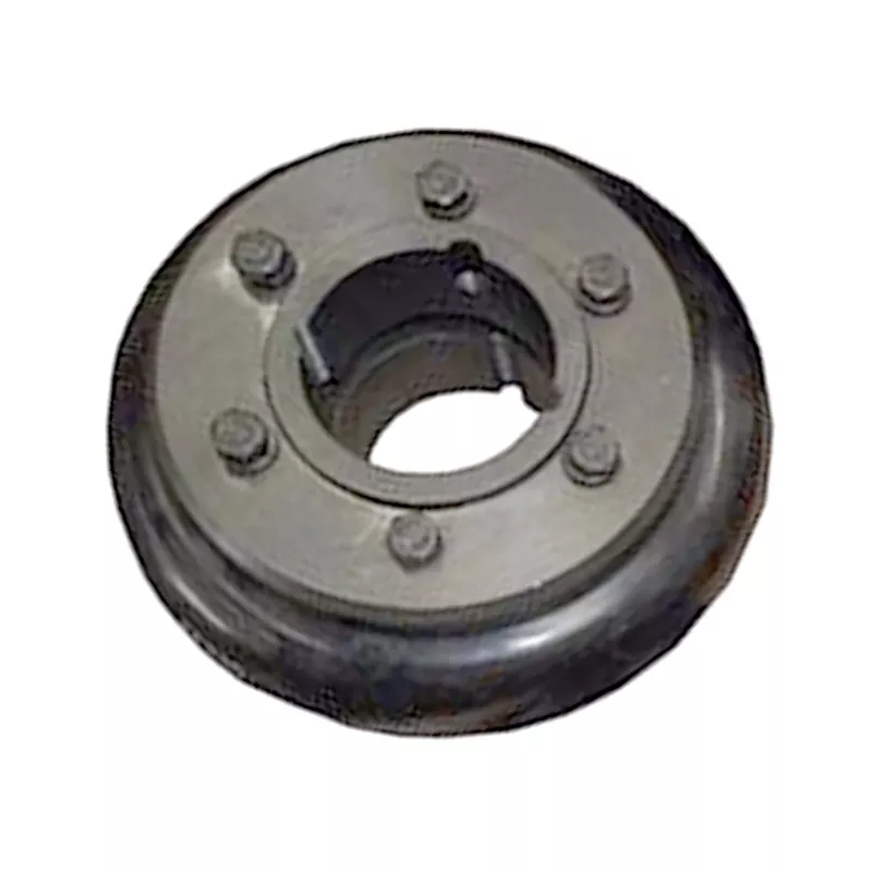
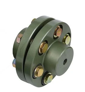
Original Excavator Parts Coupling CF-a Series Rubber Flexible Torsionally Steel Universal Shaft Coupling for Centafle
Product Display:
| Model | Outer Diameter(mm) | Inner Diameter(mm) | Hight(mm) | Diameter from Hole to Hole(mm) | Weight(kg) |
| 4A/4AS | 103 | 53 | 28 | 68 | 0.18 |
| 8A/8AS | 134 | 71 | 32 | 88 | 0.26 |
| 16A/16AS | 160 | 80 | 41 | 110 | 0.54 |
| 22A/22AS | 165 | 86 | 41 | 128 | 0.66 |
| 25A/25AS | 183 | 102 | 46 | 123 | 0.78 |
| 28A/AS | 0.88 | ||||
| 30A/30AS | 213 | 117 | 57 | 145 | 1.28 |
| 50A/50AS | 220 | 123 | 57 | 165 | 1.48 |
| 80A/80As | 225 | 120 | 65 | 167 | 1.92 |
| 90A/90As | 278 | 148 | 70 | 190 | 3.1 |
| 140A/140AS | 285 | 151 | 71 | 215 | 3.42 |
| 250A/250AS | 6.6 | ||||
| 284B | 6.34 | ||||
| 4, 4655134, EX3, ZAX460MTH, ZAX480MTH, 4636444, ZX470-3, EX470, ZAX470, ZAX450-3, ZAX450-3F, ZAX5, Atlas Copco,,
AC 385, AC 396, AC415, AC416, AC 455, AC485, AC 486, AC86, AC836, AC976, AC 6-712, 4DNV98 Chinese Brand Excavators: LGK: 6085, 200 CLG 60, 205, 220, 906, 907, 908, 920, 925, 936, CLG906C, CLG922LG YC50-8, YC60-8, YC60-8, YC135-8, YC230, YC230-8, YC230LC-8, YC360, YC85, YC50, YC85-7, YC60-7, YC135 SW50, 60, 70, 150 FR85-7, FR65, FR80, FR150-7, ZL 60, 205, 230, 360 SY55, SY60, SY215, SY230, SY210, SY220, SY310
How do you install and align a flexible coupling properly to ensure optimal performance?Proper installation and alignment of a flexible coupling are essential to ensure its optimal performance and longevity. Incorrect installation can lead to premature wear, increased vibrations, and potential equipment failure. Below are the steps to install and align a flexible coupling properly: 1. Pre-Installation Inspection: Before installation, inspect the flexible coupling and its components for any visible damage or defects. Check that the coupling’s size and specifications match the application requirements. Ensure that the shafts and equipment connected to the coupling are clean and free from debris. 2. Shaft Preparation: Prepare the shafts by removing any oil, grease, or contaminants from the surfaces that will come into contact with the coupling. Ensure that the shaft ends are smooth and free from burrs that could affect the fit of the coupling. 3. Coupling Hub Installation: Slide the coupling hubs onto the shafts, ensuring they are positioned securely and evenly on each shaft. Use a lubricant recommended by the manufacturer to facilitate the installation and ensure a proper fit. 4. Alignment: Proper alignment is critical for the performance and longevity of the flexible coupling. Align the shafts by checking both angular and parallel misalignment. Utilize precision alignment tools, such as dial indicators or laser alignment systems, to achieve accurate alignment. Follow the manufacturer’s alignment specifications and tolerance limits. 5. Tightening Fasteners: Once the shafts are properly aligned, tighten the coupling’s fasteners to the manufacturer’s recommended torque values. Gradually tighten the fasteners in a cross pattern to ensure even distribution of the load on the coupling hubs. Avoid over-tightening, as it may cause distortion or damage to the coupling. 6. Run-Out Check: After installation, perform a run-out check to verify that the coupling’s rotating components are balanced and aligned. Excessive run-out can lead to vibrations and reduce the coupling’s performance. If significant run-out is detected, recheck the alignment and address any issues that may be causing it. 7. Lubrication: Ensure that the flexible coupling is adequately lubricated, following the manufacturer’s recommendations. Proper lubrication reduces friction and wear, enhancing the coupling’s efficiency and reliability. 8. Periodic Inspection and Maintenance: Regularly inspect the flexible coupling for signs of wear, misalignment, or damage. Address any issues promptly to prevent further problems. Depending on the coupling type and application, scheduled maintenance may include re-greasing, re-alignment, or replacing worn components. Summary: Proper installation and alignment are crucial for ensuring the optimal performance and longevity of a flexible coupling. Following the manufacturer’s guidelines, inspecting the components, achieving accurate alignment, and using the appropriate lubrication are key steps in the installation process. Regular inspection and maintenance help to identify and address potential issues, ensuring the coupling continues to operate smoothly and efficiently in the mechanical system.
How does a flexible coupling handle torsional vibrations in rotating machinery?A flexible coupling is designed to handle torsional vibrations in rotating machinery by providing a degree of flexibility and damping. Torsional vibrations are oscillations that occur in the drivetrain due to torque variations, sudden load changes, or other transient events. These vibrations can lead to resonance, excessive stress, and premature failure of components. Flexible couplings mitigate torsional vibrations through the following mechanisms:
It is important to select the appropriate flexible coupling based on the specific torsional characteristics and requirements of the rotating machinery. Different applications may demand different types of couplings with varying levels of flexibility and damping. High-performance flexible couplings can effectively minimize torsional vibrations, protecting the drivetrain and connected equipment from excessive stress and potential damage. Additionally, proper alignment of the flexible coupling during installation is crucial to ensure its optimal performance in mitigating torsional vibrations. Misalignment can introduce additional stresses and exacerbate torsional issues in the system. Regular inspection and maintenance of the flexible coupling will help identify any signs of wear or damage that may affect its ability to handle torsional vibrations effectively.
Can you explain the different types of flexible coupling designs available?There are several types of flexible coupling designs available, each with its unique construction and characteristics. These designs are tailored to meet specific application requirements and address different types of misalignment and torque transmission needs. Here are some of the most common types of flexible couplings:
Each flexible coupling design has its strengths and limitations, and the choice depends on factors such as the application’s torque requirements, misalignment conditions, operating environment, and speed. Proper selection of the coupling type ensures optimal performance, efficiency, and reliability in various mechanical systems and rotating machinery.
|