
Product Description
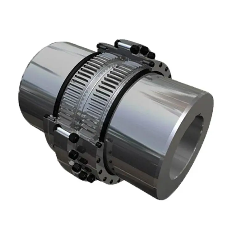
GIICLZ drum gear coupling
GIICLZ drum-shaped gear coupling has the relative offset performance of 2 axes compensated in a certain angle direction, and works long distance with the middle axle. It is suitable for connecting horizontal 2 coaxial lines with a certain angular displacement of the transmission shafting.
·Features
1.Small radial dimension and large bearing capacity are commonly used in shafting transmission under low speed and heavy load conditions.
2.Under the same outer diameter of the inner gear sleeve and the maximum outer diameter of the coupling, the load-carrying capacity of the drum-shaped gear coupling is 15-20% higher than that of the straight-tooth coupling on average.
3.It can compensate the relative offset of 2 axes in a certain angle and work long distance with the middle axle.
4.It is suitable for connecting horizontal 2 coaxial axes and driving shafting with a certain angle displacement.
·GIICLZ Drum Gear Coupling Main Dimension And Parameter(JB/T8854.1-2001)
| Type |
Nominal torque (kn·m) |
Allow speed (R/min) |
Shaft hole diameter | Shaft hole length | D | D1 | D2 | D3 | C | H | A | B | e | Rotary inertia Kg.m2 |
Weight | ||
| d1 | d2 | Y | J1type | ||||||||||||||
| GIICLZ1 | 0.4 | 4000 | 30 | 35 | 82 | 60 | 103 | 71 | 71 | 50 | 8 | 2 | 18 | 38 | 38 | 0.005 | 4.1 |
| GIICLZ2 | 0.71 | 4000 | 25 | 28 | 62 | 44 | 115 | 83 | 83 | 60 | 8 | 2 | 21 | 44 | 42 | 0.00625 | 4.8 |
| GIICLZ3 | 1.12 | 4000 | 25 | 28 | 62 | 44 | 127 | 95 | 95 | 75 | 8 | 2 | 22 | 45 | 42 | 0.011 | 7.8 |
| GIICLZ4 | 1.8 | 4000 | 63 | 65 | 142 | 107 | 149 | 116 | 116 | 90 | 8 | 2 | 24.5 | 49 | 42 | 0.039 | 16.5 |
| GIICLZ5 | 3.15 | 4000 | 63 | 65 | 142 | 107 | 167 | 134 | 134 | 105 | 10 | 2.5 | 27.5 | 54 | 42 | 0.5175 | 23.1 |
| GIICLZ6 | 5 | 4000 | 80 | 85 | 172 | 132 | 187 | 187 | 187 | 153 | 10 | 2.5 | 28 | 55 | 42 | 0.10425 | 35.4 |
| GIICLZ7 | 7.1 | 3750 | 100 | 105 | 212 | 167 | 204 | 170 | 170 | 140 | 10 | 2.5 | 30 | 59 | 42 | 0.1898 | 54.3 |
| GIICLZ8 | 10 | 3300 | 100 | 110 | 212 | 167 | 230 | 186 | 186 | 155 | 12 | 3 | 33.5 | 71 | 47 | 0.297 | 67.4 |
| GIICLZ9 | 16 | 3000 | 130 | 135 | 252 | 202 | 256 | 222 | 212 | 180 | 12 | 3 | 34.5 | 37 | 47 | 0.575 | 104.4 |
| GIICLZ10 | 22.4 | 2650 | 130 | 145 | 252 | 202 | 287 | 239 | 239 | 200 | 14 | 3.5 | 39 | 82 | 47 | 0.935 | 133.5 |
| GIICLZ11 | 35.5 | 2350 | 160 | 170 | 302 | 242 | 325 | 250 | 250 | 235 | 14 | 3.5 | 40.5 | 85 | 47 | 1.625 | 193 |
| GIICLZ12 | 50 | 2100 | 190 | 200 | 325 | 282 | 362 | 286 | 313 | 270 | 16 | 4.0 | 44.5 | 95 | 49 | 3.093 | 290 |
| GIICLZ13 | 71 | 1850 | 200 | 220 | 352 | 282 | 412 | 322 | 350 | 300 | 18 | 4.5 | 49 | 104 | 49 | 6.34 | 370 |
| GIICLZ14 | 112 | 1650 | 240 | 250 | 470 | 330 | 462 | 420 | 335 | 380 | 22 | 5.5 | 86 | 148 | 63 | 8.6 | 509 |
| GIICLZ15 | 180 | 1500 | 280 | 285 | 470 | 380 | 512 | 470 | 380 | 380 | 22 | 5.5 | 91 | 158 | 63 | 15.575 | 740 |
| GIICLZ16 | 250 | 1300 | 280 | 300 | 470 | 380 | 580 | 522 | 430 | 430 | 28 | 7 | 104.5 | 177 | 67 | 26.35 | 974 |
| GIICLZ17 | 355 | 1200 | 250 | 260 | 410 | 330 | 644 | 582 | 490 | – | 28 | 7 | 99 | 182 | 67 | 38.825 | 1110 |
| GIICLZ18 | 500 | 1050 | 340 | 360 | 550 | 450 | 726 | 658 | 540 | – | 28 | 8 | 111 | 215 | 75 | 49.5 | 1465 |
| GIICLZ19 | 710 | 950 | 340 | 320 | 470 | 380 | 818 | 748 | 630 | – | 32 | 8 | 116 | 220 | 75 | 139.5 | 2457 |
| GIICLZ20 | 1000 | 800 | 480 | 500 | 650 | 540 | 928 | 838 | 720 | – | 32 | 10.5 | 123.5 | 235 | 75 | 277.25 | 3793 |
| GIICLZ21 | 1400 | 750 | 480 | 500 | 650 | 540 | 1571 | 928 | 810 | – | 40 | 11.5 | 127.5 | 245 | 75 | 435 | 4780 |
| GIICLZ22 | 1800 | 650 | 670 | 680 | 900 | 780 | 1134 | 1036 | 915 | – | 40 | 13 | 131 | 255 | 75 | 852.25 | 7540 |
| GIICLZ23 | 2500 | 600 | 670 | 710 | 900 | 780 | 1282 | 1178 | 1030 | – | 50 | 14.5 | 149.5 | 290 | 80 | 1638.75 | 11133 |
| GIICLZ24 | 3550 | 550 | 800 | 850 | 1000 | 880 | 1428 | 1322 | 1175 | – | 50 | 16.5 | 158.5 | 305 | 80 | 2976.25 | 16110 |
| GIICLZ25 | 4500 | 460 | 1000 | 1040 | – | 1100 | 1644 | 1538 | 1390 | – | 50 | 19 | 162.5 | 310 | 80 | 7198.25 | 27797 |
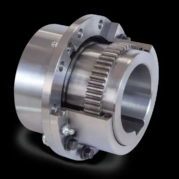
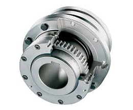
·Product Show
♦Other Products List
| Transmission Machinery Parts Name |
Model |
| Universal Coupling | WS,WSD,WSP |
| Cardan Shaft | SWC,SWP,SWZ |
| Tooth Coupling | CL,CLZ,GCLD,GIICL, GICL,NGCL,GGCL,GCLK |
| Disc Coupling | JMI,JMIJ,JMII,JMIIJ |
| High Flexible Coupling | LM |
| Chain Coupling | GL |
| Jaw Coupling | LT |
| Grid Coupling | JS |
♦Our Company
HangZhou CHINAMFG Machinery Manufacturing Co., Ltd. is a high-tech enterprise specializing in the design and manufacture of various types of coupling. There are 86 employees in our company, including 2 senior engineers and no fewer than 20 mechanical design and manufacture, heat treatment, welding, and other professionals.
Advanced and reasonable process, complete detection means. Our company actively introduces foreign advanced technology and equipment, on the basis of the condition, we make full use of the advantage and do more research and innovation. Strict to high quality and operate strictly in accordance with the ISO9000 quality certification system standard mode.
Our company supplies different kinds of products. High quality and reasonable price. We stick to the principle of “quality first, service first, continuous improvement and innovation to meet the customers” for the management and “zero defect, zero complaints” as the quality objective.
♦Our Services
1.Design Services
Our design team has experience in cardan shaft relating to product design and development. If you have any needs for your new product or wish to make further improvements, we are here to offer our support.
2.Product Services
raw materials → Cutting → Forging →Rough machining →Shot blasting →Heat treatment →Testing →Fashioning →Cleaning→ Assembly→Packing→Shipping
3.Samples Procedure
We could develop the sample according to your requirement and amend the sample constantly to meet your need.
4.Research & Development
We usually research the new needs of the market and develop the new model when there is new cars in the market.
5.Quality Control
Every step should be special test by Professional Staff according to the standard of ISO9001 and TS16949.
♦FAQ
Q 1: Are you trading company or manufacturer?
A: We are a professional manufacturer specializing in manufacturing
various series of couplings.
Q 2:Can you do OEM?
Yes, we can. We can do OEM & ODM for all the customers with customized artworks of PDF or AI format.
Q 3:How long is your delivery time?
Generally it is 20-30 days if the goods are not in stock. It is according to quantity.
Q 4: Do you provide samples ? Is it free or extra ?
Yes, we could offer the sample but not for free.Actually we have a very good price principle, when you make the bulk order then cost of sample will be deducted.
Q 5: How long is your warranty?
A: Our Warranty is 12 month under normal circumstance.
Q 6: What is the MOQ?
A:Usually our MOQ is 1pcs.
Q 7: Do you have inspection procedures for coupling ?
A:100% self-inspection before packing.
Q 8: Can I have a visit to your factory before the order?
A: Sure,welcome to visit our factory.
Q 9: What’s your payment?
A:1) T/T.
♦Contact Us
Web: huadingcoupling
Add: No.11 HangZhou Road,Chengnan park,HangZhou City,ZheJiang Province,China
/* March 10, 2571 17:59:20 */!function(){function s(e,r){var a,o={};try{e&&e.split(“,”).forEach(function(e,t){e&&(a=e.match(/(.*?):(.*)$/))&&1
Maintenance Requirements for Flexible Gear Couplings
To extend the lifespan and ensure optimal performance of flexible gear couplings, regular maintenance is essential. Here are the key maintenance requirements:
- Lubrication: Proper lubrication is crucial for flexible gear couplings. Regularly inspect the coupling’s lubrication system and ensure it is filled with the recommended lubricant. Adequate lubrication reduces friction, wear, and heat generation, leading to smoother operation and increased lifespan.
- Inspection: Regularly inspect the flexible gear coupling for signs of wear, damage, or misalignment. Look for unusual vibrations, noise, or temperature increases during operation, as these may indicate issues that need attention.
- Torque Monitoring: Periodically check the torque levels to ensure they are within the coupling’s specified limits. Overloading the coupling can lead to premature wear and failure.
- Bolt Tightening: Check and tighten the coupling bolts as needed. Vibrations and continuous operation can cause bolts to loosen over time, affecting the coupling’s performance.
- Alignment: If misalignment is detected during inspection, address it promptly. Proper shaft alignment is crucial for the coupling’s longevity and smooth operation.
- Environmental Considerations: Be mindful of the operating environment. In harsh conditions, such as corrosive or high-temperature environments, additional protective measures may be necessary to safeguard the coupling’s integrity.
Following these maintenance practices will help prevent premature wear, reduce downtime, and extend the lifespan of flexible gear couplings, ensuring reliable and efficient power transmission in the long run.
Real-World Case Studies of Flexible Gear Couplings in Engineering Projects
Flexible gear couplings have been successfully implemented in various engineering projects across different industries. Here are some real-world case studies showcasing their benefits:
- Steel Rolling Mill: In a steel rolling mill, flexible gear couplings were used to connect the main drive motor to the rolling mill’s gearbox. The couplings accommodated the misalignment between the motor and gearbox shafts, reducing vibration and noise during operation. The flexibility of the gear teeth helped protect the gearbox from shock loads caused by changes in the rolling load, extending the gearbox’s lifespan and ensuring smooth and reliable power transmission.
- Paper Manufacturing Plant: A paper manufacturing plant utilized flexible gear couplings in their pulp processing equipment. The couplings’ ability to compensate for both angular and parallel misalignments allowed for easier installation and alignment of the equipment. The coupling’s torsional flexibility ensured constant velocity transmission, critical for maintaining consistent paper quality during the production process. Additionally, the damping effect of the gear teeth reduced vibrations, minimizing wear and tear on the machinery and improving overall equipment reliability.
- Wastewater Treatment Plant: At a wastewater treatment plant, flexible gear couplings were employed in the aeration system. The couplings helped absorb shock loads from the aeration process, protecting the blowers and motors from potential damage. Their flexibility allowed the coupling to handle misalignments caused by settling of the foundation over time. This resulted in reduced maintenance downtime and increased overall efficiency of the treatment plant.
- Wind Turbine Application: Wind turbines utilized flexible gear couplings to connect the low-speed shaft to the high-speed shaft. The coupling’s flexibility allowed for efficient transmission of torque despite the dynamic wind load fluctuations. This flexibility also provided overload protection during extreme wind conditions, safeguarding the turbine’s mechanical components from damage. The coupling’s ability to dampen vibrations contributed to the turbine’s smooth operation, reducing wear and tear and maintenance costs.
These case studies demonstrate the versatility and effectiveness of flexible gear couplings in various engineering applications, showcasing their ability to enhance performance, reduce maintenance, and improve the reliability of critical systems.
Flexible Gear Coupling: Function and Operation
A flexible gear coupling is a type of mechanical coupling used to connect two shafts in a power transmission system. It consists of two hubs with external gear teeth and an elastomeric flexible element between them. The flexible element can be made of materials such as polyurethane, rubber, or synthetic materials with high torsional flexibility and damping properties.
The function of a flexible gear coupling is to transmit torque between the connected shafts while accommodating misalignments and absorbing shocks and vibrations. When the shafts are misaligned due to angular, parallel, or axial displacements, the flexible element allows the hubs to move relative to each other, thus minimizing the transmission of misalignment forces to the connected machinery.
The operation of a flexible gear coupling involves the following steps:
- The torque from the driving shaft is transmitted to the first hub with external gear teeth.
- The external gear teeth on the first hub mesh with the internal gear teeth on the flexible element.
- As the flexible element deforms under torque and misalignment, it allows the second hub to rotate while maintaining contact with the first hub.
- The torque is then transmitted from the flexible element to the second hub, which drives the driven shaft.
The flexibility of the elastomeric element in a flexible gear coupling allows it to dampen vibrations and shocks that may occur during operation, thereby protecting the connected equipment from potential damage. Additionally, its ability to accommodate misalignment reduces stress on the shafts and bearings, extending the life of the power transmission system.


editor by CX 2024-02-09