
Product Description
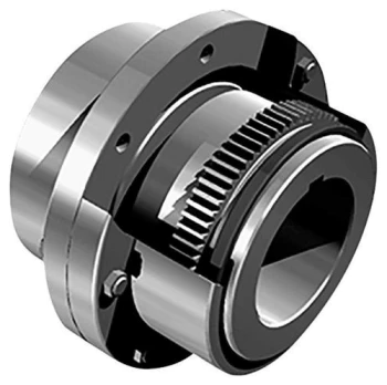
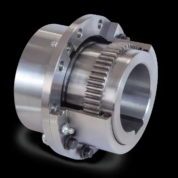
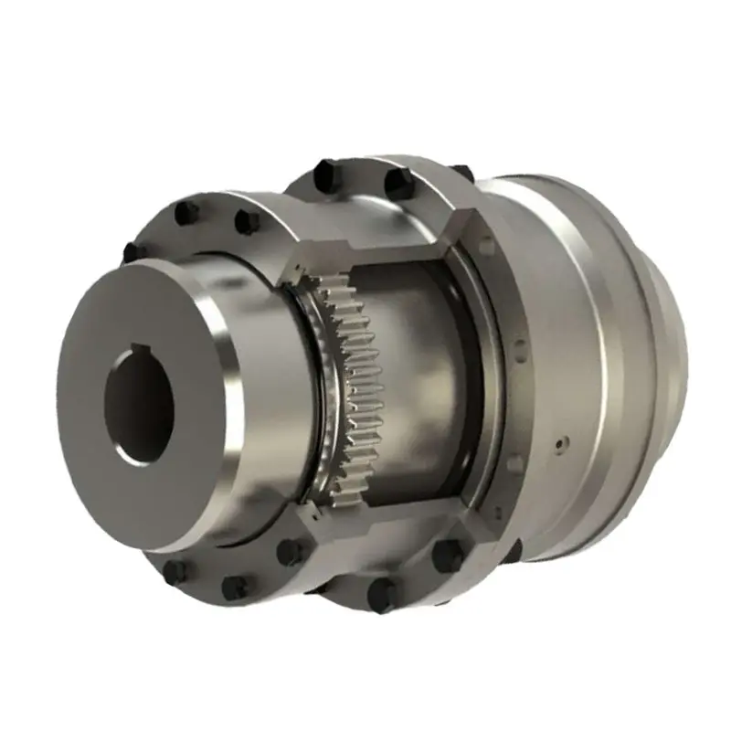
GFC-80X114 Manufacturer Flexible Clamp Style GFC Shaft Spider Gear Motor Jaw Coupling
GFC-80X114 Manufacturer Flexible Clamp Style GFC Shaft Spider Gear Motor Jaw Coupling
| model parameter | common bore diameter d1,d2 | ΦD | L | LF | LP | F | M | tightening screw torque (N.M) |
| GFC-14X22 | 3,4,5,6,6.35 | 14 | 22 | 14.3 | 6.6 | 5.0 | M2.5 | 1.0 |
| GFC-20×25 | 3,4,5,6,6.35,7,8,9,9.525,10 | 20 | 25 | 16.7 | 8.6 | 5.9 | M3 | 1.5 |
| GFC-20X30 | 3,4,5,6,6.35,7,8,9,9.525,10 | 20 | 30 | 19.25 | 8.6 | 5.9 | M3 | 1.5 |
| GFC-25X30 | 4,5,6,6.35,7,8,9,9.525,10,11,12 | 25 | 30 | 20.82 | 11.6 | 8.5 | M4 | 2.5 |
| GFC-25X34 | 4,5,6,6.35,7,8,9,9.525,10,11,12 | 25 | 34 | 22.82 | 11.6 | 8.5 | M4 | 2.5 |
| GFC-30×35 | 5,6,6.35,7,8,9,10,11,12,12.7,14,15,16 | 30 | 35 | 23 | 11.5 | 10 | M4 | 2.5 |
| GFC-30X40 | 5,6,6.35,7,8,9,10,11,12,12.7,14,15,16 | 30 | 40 | 25 | 11.5 | 10 | M4 | 2.5 |
| GFC-40X50 | 6,8,9,10,11,12,12.7,14,15,16,17,18,19,20,22,24 | 40 | 50 | 32.1 | 14.5 | 14 | M5 | 7 |
| GFC-40X55 | 6,8,9,10,11,12,12.7,14,15,16,17,18,19,20,22,24 | 40 | 55 | 34.5 | 14.5 | 14 | M5 | 7 |
| GFC-40X66 | 6,8,910,11,12,12.7,14,15,16,17,18,19,20,22,24 | 40 | 66 | 40 | 14.5 | 14 | M5 | 7 |
| GFC-55X49 | 10,11,12,12.7,14,15,16,17,18,19,20,22,24,25,28,30,32 | 55 | 49 | 32 | 16.1 | 13.5 | M6 | 12 |
| GFC-55X78 | 8,10,12,12.7,14,15,16,17,18,19,20,22,24,25,28,30,32 | 55 | 78 | 46.4 | 16.1 | 19 | M6 | 12 |
| GFC-65X80 | 14,15,16,17,18,19,20,22,24,25,28,30,32,35,38,40 | 65 | 80 | 48.5 | 17.3 | 14 | M8 | 20 |
| GFC-65X90 | 14,15,16,17,18,19,20,22,24,25,28,30,32,35,38,40 | 65 | 90 | 53.5 | 17.3 | 22.5 | M8 | 20 |
| GFC-80X114 | 19,20,22,24,25,28,30,32,35,38,40,42,45 | 80 | 114 | 68 | 22.5 | 16 | M8 | 20 |
| GFC-95X126 | 19,20,22,24,25,28,30,32,35,38,40,42,45,50,55 | 95 | 126 | 74.5 | 24 | 18 | M10 | 30 |
| model parameter | Rated torque (N.M)* |
allowable eccentricity (mm)* |
allowable deflection angle (°)* |
allowable axial deviation (mm)* |
maximum speed rpm |
static torsional stiffness (N.M/rad) |
moment of inertia (Kg.M2) |
Material of shaft sleeve | Material of shrapnel | surface treatment | weight (g) |
| GFC-14X22 | 5.0 | 0.1 | 1 | ±02 | 10000 | 50 | 1.0×10⁻⁶ | High strength aluminum alloy | Polyurethane imported from Germany | Anodizing treatment | 10 |
| GFC-20X25 | 5.0 | 0.1 | 1 | ±02 | 10000 | 50 | 1.0×10⁻⁶ | 15 | |||
| GFC-20X30 | 5.0 | 0.1 | 1 | ^02 | 10000 | 53 | 1.1×10⁻⁶ | 19 | |||
| GFC-25X30 | 10 | 0.1 | 1 | 10000 | 90 | 5.2X10⁻⁶ | 33 | ||||
| GFC-25X34 | 10 | 0.1 | 1 | £)2 | 10000 | 90 | 5.2×10⁻⁶ | 42 | |||
| GFC-30X35 | 12.5 | 0.1 | 1 | ±02 | 10000 | 123 | 6.2×10⁻⁶ | 50 | |||
| GFC-30×40 | 12.5 | 0.1 | 1 | 102 | 10000 | 123 | 6.2×10⁻⁶ | 60 | |||
| GFC-40X50 | 17 | 0.1 | 1 | 8000 | 1100 | 3.8×10⁻⁵ | 115 | ||||
| GFC-40X55 | 17 | 0.1 | 1 | ±02 | 8000 | 1100 | 3.8×10⁻⁵ | 127 | |||
| GFC-40X66 | 17 | 0.1 | 1 | 7000 | 1140 | 3.9×10⁻⁵ | 154 | ||||
| GFC-55X49 | 45 | 0.1 | 1 | ±02 | 6500 | 2350 | 1.6×10⁻³ | 241 | |||
| GFC-55X78 | 45 | 0.1 | 1 | 102 | 6000 | 2500 | 1.6×10⁻³ | 341 | |||
| GFC-65X80 | 108 | 0.1 | 1 | ±02 | 5500 | 4500 | 3.8×10⁻³ | 433 | |||
| GFC-65X90 | 108 | 0.1 | 1 | ±02 | 5500 | 4800 | 3.8×10⁻³ | 583 | |||
| GFC-80X114 | 145 | 0.1 | 1 | £)2 | 4500 | 5000 | 1.8×10⁻³ | 1650 | |||
| GFC-95X126 | 250 | 0.1 | 1 | ±02 | 4000 | 5000 | 2.0×10⁻³ | 1000 |
/* January 22, 2571 19:08:37 */!function(){function s(e,r){var a,o={};try{e&&e.split(“,”).forEach(function(e,t){e&&(a=e.match(/(.*?):(.*)$/))&&1
Materials Used in Manufacturing Flexible Gear Couplings and Their Impact on Performance
Flexible gear couplings are designed to transmit torque while accommodating misalignments and reducing vibrations. The choice of materials for manufacturing these couplings plays a crucial role in their overall performance and suitability for specific applications. Some common materials used in flexible gear couplings include:
- Steel: Steel is a popular material for flexible gear couplings due to its high strength and durability. It can handle substantial torque loads and provides good resistance to wear and fatigue. Steel couplings are commonly used in heavy-duty applications, such as steel mills, mining, and power generation.
- Stainless Steel: Stainless steel is used when corrosion resistance is required, making it suitable for applications in corrosive environments like the marine, chemical, and petrochemical industries.
- Alloy Steel: Alloy steel is used to improve specific properties, such as hardness and heat resistance. It is often employed in high-temperature applications found in steel processing and power generation.
- Cast Iron: Cast iron is known for its excellent wear resistance and damping capabilities. It is used in applications where shock absorption and vibration reduction are critical, such as pumps and compressors.
- Aluminum: Aluminum is lightweight and offers good corrosion resistance, making it suitable for applications where weight reduction is important, such as aerospace and certain industrial machinery.
- Bronze: Bronze is used for its self-lubricating properties and resistance to wear. It is often found in couplings used in low-speed applications, such as conveyor systems.
- Nylon and Plastics: Nylon and other plastics are used in some couplings where electrical isolation and lightweight properties are essential, such as in medical equipment and certain automation systems.
The selection of materials depends on the specific requirements of the application, including torque, speed, temperature, environmental conditions, and the presence of corrosive substances. Proper material selection ensures that the flexible gear coupling can operate efficiently and reliably, providing optimal performance and minimizing maintenance needs.
Real-World Case Studies of Flexible Gear Couplings in Engineering Projects
Flexible gear couplings have been successfully implemented in various engineering projects across different industries. Here are some real-world case studies showcasing their benefits:
- Steel Rolling Mill: In a steel rolling mill, flexible gear couplings were used to connect the main drive motor to the rolling mill’s gearbox. The couplings accommodated the misalignment between the motor and gearbox shafts, reducing vibration and noise during operation. The flexibility of the gear teeth helped protect the gearbox from shock loads caused by changes in the rolling load, extending the gearbox’s lifespan and ensuring smooth and reliable power transmission.
- Paper Manufacturing Plant: A paper manufacturing plant utilized flexible gear couplings in their pulp processing equipment. The couplings’ ability to compensate for both angular and parallel misalignments allowed for easier installation and alignment of the equipment. The coupling’s torsional flexibility ensured constant velocity transmission, critical for maintaining consistent paper quality during the production process. Additionally, the damping effect of the gear teeth reduced vibrations, minimizing wear and tear on the machinery and improving overall equipment reliability.
- Wastewater Treatment Plant: At a wastewater treatment plant, flexible gear couplings were employed in the aeration system. The couplings helped absorb shock loads from the aeration process, protecting the blowers and motors from potential damage. Their flexibility allowed the coupling to handle misalignments caused by settling of the foundation over time. This resulted in reduced maintenance downtime and increased overall efficiency of the treatment plant.
- Wind Turbine Application: Wind turbines utilized flexible gear couplings to connect the low-speed shaft to the high-speed shaft. The coupling’s flexibility allowed for efficient transmission of torque despite the dynamic wind load fluctuations. This flexibility also provided overload protection during extreme wind conditions, safeguarding the turbine’s mechanical components from damage. The coupling’s ability to dampen vibrations contributed to the turbine’s smooth operation, reducing wear and tear and maintenance costs.
These case studies demonstrate the versatility and effectiveness of flexible gear couplings in various engineering applications, showcasing their ability to enhance performance, reduce maintenance, and improve the reliability of critical systems.
Proper Installation of Flexible Gear Couplings for Optimal Performance and Reliability
Proper installation of a flexible gear coupling is crucial to ensure its optimal performance, reliability, and longevity. Here are the steps to follow for a successful installation:
- Inspect the Coupling: Before installation, carefully inspect the coupling components, including the hubs, gear teeth, and flexible element, for any damage or defects.
- Clean the Components: Ensure that all components are clean and free from dirt, debris, and any contaminants that could affect the coupling’s performance.
- Check Alignment: Verify that the shafts of the connected equipment are properly aligned within the manufacturer’s recommended tolerances. Misalignment can lead to premature wear and failure of the coupling.
- Grease or Lubricate: Apply the appropriate coupling lubricant or grease to the gear teeth and the flexible element. Lubrication helps reduce friction, heat generation, and wear.
- Assemble the Coupling: Carefully assemble the coupling by aligning the gear teeth of the hubs and the internal sleeve. Follow the manufacturer’s guidelines for the correct orientation and positioning.
- Tighten Fasteners: Gradually tighten the fasteners, such as bolts or screws, in a cross-pattern to ensure even pressure distribution. Do not overtighten, as it can cause deformation of the coupling components.
- Perform a Trial Run: After installation, perform a trial run to check for any abnormalities, unusual noises, or vibrations. Monitor the coupling during the trial run to detect any potential issues.
- Regular Maintenance: Implement a regular maintenance schedule to inspect and lubricate the coupling periodically. Follow the manufacturer’s maintenance guidelines to ensure the coupling’s continued performance and reliability.
- Replace Worn Components: If any components of the coupling show signs of wear or damage during maintenance inspections, replace them promptly to prevent further issues.
It is essential to follow the manufacturer’s installation instructions and guidelines specific to the flexible gear coupling model to achieve the best results. Proper installation enhances the coupling’s ability to handle misalignment, transmit torque efficiently, and ensure reliable operation in the power transmission system.


editor by CX 2024-05-02